General Information
This website catalogue is divided by switch types: toggle switches, pushbutton switches, slide switches, dual-in-line switches, rotary coded switches, rotary switches, encoder, LED’s and membranes.
The chapters include professional, semi-professional and low-cost components
The technical specification for each series is specifically stated. Unless otherwise specified, the figures for contact rating apply for the standard version.
For several series, especially MT… and MP…, the following is available:
Standard version: | silver or silver-plated contacts and terminals |
Configuration B: | gold-plated (over Nickel) contacts and terminals |
Configuration G: | gold-plated (over silver) contacts and terminals |
All switches are sealed on the terminal side.
Switches for SMT as well as most series for PCB mounting are generally fully washable.
Unless otherwise specified, components for auto- (wave-) soldering are limited to pre-heat max. 60s, max. 100 °C, soldering max. 5s, max. 260 °C.
Signs and symbols:
ESD: | component is ESD-resistant. Resistance is depending from switch size and is listed in the technical data. |
IP 67: | component has an approved IP rating or is according to an IP rating. |
CE: | our products meet all relevant regulations |
| all products in the catalogue are RohS/REACH compliant at the time of publication, for Details see REach/RohS on knitter-switch.com |
| IR-reflow soldering according to JEDEC ST-020 D |


Type naming/switching functions
A group of a maximum of 4 identification letters is followed by up to 4 digits (excepted membranes and some
switches with specific features).
The letters are specific for the type of actuation, the digits describes certain technical features.
This is followed by the characteristic letters for the different switching functions (if there are).
off - on | A | |||
on - (mom) | B | |||
off - mom | C | First column is ued for 1/3 pole-, | ||
on - on | D | N | ||
on off on | E | P | ||
mom: momentary on | mom - on | F | R | |
(mom):momentary off | mom off mom | G | S | |
mom off on | H | T | ||
on on on | EA | PA | ||
mom on mom | SA | |||
mom on on | TA |
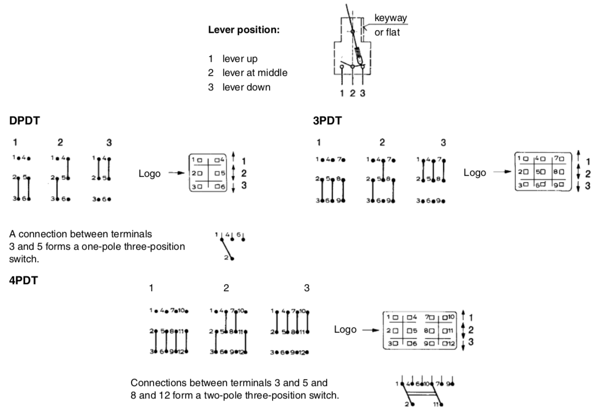
For all toggle switches, a dot on the top of the switching function table indicates the switching position with the lever in the direction of the keyway or the flatted thread. The closed contacts are always opposite to the position of the lever.
For PA, SA and TA types the poles are switched separately as shown in the diagram below: